4 Implementation
4.1 Equipment
The system is implemented on a Sun SPARCstation 10 with a Data Cell
S2200 frame grabber. Images are provided by two monochrome CCD
cameras, which view the operator's hand and the working area from
a distance of about 1.6 metres. The angle between the cameras is about
30 degrees.
A Scorbot ER-7 robot arm is also controlled by the Sun
(figure 4).
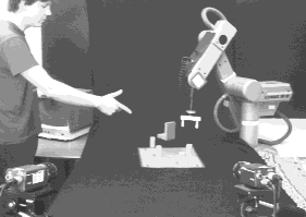
Figure 4: Arrangement of the stereo cameras, table and robot.
The cameras view the robot, workspace and operator's hand from a
distance of about 1.6m.
4.2 Experiment
Setup
In this experiment, the corners of a coloured rectangle on the
table-top are used to define the working coordinate system.
A pair of finger-trackers (one for each camera) is initialised, one
after the other, by the operator holding his hand up to a template in
the image and waiting a few seconds while it `moulds' itself to the
contours of the finger and thumb. Once both trackers are running,
the hand can be used as an input device by pointing to places on the
table-top.
In our implementation, the position and orientation of the finger,
and the indicated point on the plane, are updated about 10 times
per second.
Performance
Figure 5 shows the system in operation. The corners of
the white rectangle are the four reference points,
and the overlaid square shows the position of the indicated point.
Movements of the operator's hand cause corresponding
movements of this point in real time.
Visual tracking can follow the hand successfully for several minutes at
a time; however, abrupt or non-rigid hand movements can cause one or
both of the trackers to fail. Because it samples the image only
locally, a failed tracker will not correct itself
unless the user makes a special effort to recapture it.
Users report that the recovered point does not always correspond
to their subjective pointing direction, which is related to the
line of sight from eye to fingertip as well as the orientation of
the finger itself. Initial subjective estimates of accuracy are in the order
of 20-40mm. If the user receives feedback by viewing the system's
behaviour on a monitor screen, a resolution within 10mm can be
achieved. It is a natural human skill to servo the motion
of one's hand to control a cursor or other visual indication.
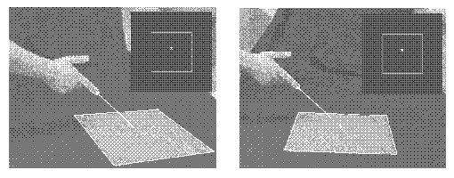
Figure 5: Stereo views of a pointing hand.
The two views are shown
side by side. In each view an active contour is tracking the hand.
The inlaid square is a representation of the
indicated point in working plane coordinates.
4.3 Accuracy evaluation
To evaluate our system, we calculate the
uncertainty of the images of the hand and reference points in our
experimental setup. Using Monte Carlo methods, these are propagated into
working plane coordinates, to assess the accuracy of the indicated point.
Finger tracker uncertainty
We can obtain a measure of uncertainty for the finger's position and
orientation in the image by considering the
residual offsets between modelled and observed image edges.
These are the components of the normal offsets that remain after
fitting a pair of parallel lines to model the index finger's occluding
edges, with least-squares perpendicular error.
They take into account the effects of image noise and occlusion, as
well as pixel quantisation effects, and mismatches between the
model and the actual shape of the index finger.
These offsets indicate that the image position of the
finger's midline can be determined to sub-pixel accuracy (standard
deviation typically 0.3 pixels), and the
orientation to an accuracy of 0.6 degrees.
From this uncertainty measure we calculate +/- 2 std dev
bounds on lines li and
li';
and, by projecting these onto the ground plane, estimate the
uncertainty in the indicated point.
Figure 6 shows the results for three different
configurations of the cameras, with a 95% confidence ellipse drawn
around the indicated point. The constraint line uncertainties are much
the same in each trial, but the uncertainty on the indicated point
varies according to the separation between the stereo views:
when the cameras are close together, the constraint lines are
nearly parallel and tracker uncertainty is very significant (figure
6a); as the baseline is increased and the stereo views
become more distinct, the constraint lines
meet at a greater angle and accuracy is improved (figure 6c).
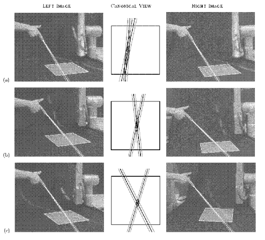
Figure 6:
Indicated point uncertainty for 3 different camera configurations.
2 std.dev bounds for the pointing lines, their projections
into working plane coordinates, and error ellipses for the indicated
point, when the angle between stereo views is
(a) 7 degrees (b) 16 degrees (c) 34 degrees.
The uncertainty is greatest when the camera angle is small and
the constraint lines nearly parallel.
Reference point uncertainty
In the above experiments, reference points are indentified in the
images by hand, and we assume an uncertainty of 1 pixel standard
deviation (in an application, techniques exist to allow points or
lines to be localised to higher accuracy, and errors may be reduced by
observing more than 4 corresponding points - this is therefore a
rather conservative estimate of accuracy).
We used
Monte Carlo simulations (based around real-world configurations of
cameras, hand and table) to assess the impact of this uncertainty on
the coordinates of the indicated point. The results (table 1)
show that this source of error is less significant
than the tracker uncertainty, and confirm that the system is not
especially sensitive to errors in the reference point image coordinates.
Again, the errors are most significant when the camera separation is small.
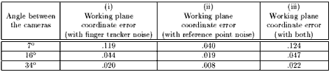
Table 1: Simulated RMS error in working plane coordinates, due to
(i) tracker uncertainty derived from `residual offsets' as
detailed above; (ii) reference point image noise, 1 pixel std dev in each
image; (iii) both.
A value of 1.0 would correspond to a positioning uncertainty of about 40cm (the
width of the reference point rectangle).
Experimental accuracy
Ground truth about the position and orientation of a human finger is,
of course, very difficult to measure without intrusive equipment that
could interfere with our stereo vision system. We therefore tested the
accuracy of the pointing system using an artificial pointing device
(figure 7).
The test pointer was a white cylinder,
about 15cm long, bounded by black end stops and wrapped around a rod
which could be positioned by the robot arm to an accuracy of about 1mm.
Whilst not identical to a human hand, it had approximately the same
dimensions and was tracked in a similar manner.
A number of trials were carried out with the vision system tracking the
rod as it was aligned with points on a grid on the target surface.
The RMS error was 2.3% of the working plane coordinates, or 9mm in
a 40cm workspace. The maximum reported error was 3.7% (15mm).
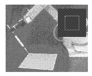
Figure 7: Mechanical pointing device used to test the accuracy of our
system.
We aligned the rod with known points on the workspace, and
recorded its coordinates as recovered by the vision system.
4.4 Robot control application
The proposed application for this stereo pointing system is to control
a robot manipulator as it grasps and places small objects on a
flat table-top.
Setup
Here the reference points are defined by observing the
robot gripper itself as it visits 4 points in a plane (using active
contours similar to those which track the pointing hand
[16]).
This not only
defines the working coordinate system but relates it to the robot's
own world coordinate system. Finger-trackers are then initialised as
before.
Performance
The robot is now instructed to move repeatedly to where the hand is
pointing, in a horizontal working plane raised 50mm above the table-top.
By watching the robot's motion, the operator is provided with a source
of direct feedback of the system's output, allowing him or her to correct for
systematic errors between subjective and observed pointing direction,
and align the gripper over objects in the robot's workspace.
When the distance between hand and workspace is large, the system
is sensitive to small changes in index finger orientation
(as one would expect). To reduce this sensitivity, the operator
maintains a steep angle to the horizontal, and points from a distance of
less than 50cm from the plane, whilst still keeping his or her hand clear
of the robot.
One can then comfortably position the gripper with sufficient accuracy
to pick up small objects (figure 8).
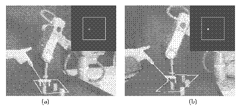
Figure 8: Gestural control of robot position for grasping,
seen in stereo.
The robot gripper servos to the position indicated
by the pointing hand; here it is being instructed to align itself with
the small wooded block to be grasped.
The four reference points (white rectangle) were defined by the
robot's gripper in a plane 50mm above the table.
Next
Contents